There is really not too much place on rocker switches to write much information. And yet you still can find quite a lot in there. So read with us what Marquardt writes to us. It will not take a lot of time and it is worth reading it.
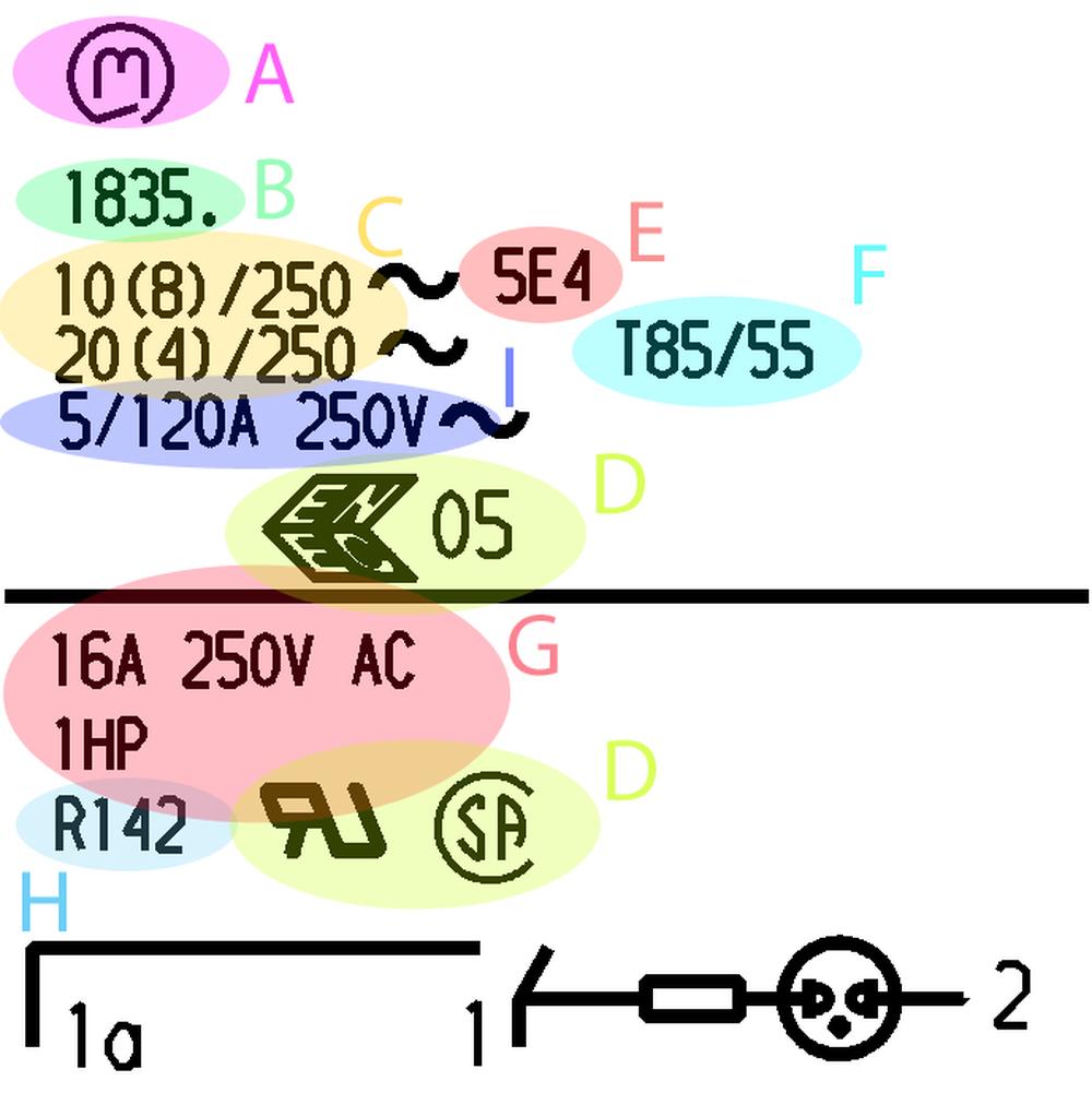
A. Marquardt logo
B. Marquardt Series
C. Rating for alternating current voltage (AC)
The electrical reference values, i.e. the maximum permissible electrical loads in continuous operation, are specified for the respective switch series. Most Marquardt switches are suitable for ohmic resistance load and motor load. In the specification of the reference power using the bracket notation, e.g. 16 (4) A 250 V AC, the value in front of the brackets indicates the switch-off current and the value in brackets the nominal motor current.
G. Rating for alternating current voltage (AC) (USA, Canada)
In switches which are additionally approved by test bodies in the USA (UL) and Canada (CSA) the corresponding ratings according to North American standards are listed additionally. The motor loads may also be shown as (Horse Power) values according to North American conventions. Mechanically, one horsepower (1HP) is equal to 33,000 pounds being moved 1 foot in 1 minute (or 33,000ft-lb/min). One horsepower (1HP) is also equal to 746 watts of electrical power. An AC motor has six-eight times higher consumption when first turned on comparing to running engine. If a horsepower rating is listed, it indicates the switch is appropriate for the use on motor loads that are rated at the given horsepower. If there is no horsepower rating listed, switches are tested to an inductive/non-horsepower load at 75% of the power factor.I. Inrush current
Short capacitive peak currents mainly occur when switching devices with power supply units (e.g. computers, printers, fax machines, etc.). The duration of these currents is typically < 10 ms. The test conditions with a special test circuit are defined in EN 61058-1 or IEC 61058-1. Values of the possible capacitive inrush currents are available for most of our appliance switches. They are labeled with the specification of the continuous current and the maximum inrush current as well as the voltage, e.g. 5/100 A 250 V AC. Guideline for the inductive inrush current is 6 times of the specified motor current described in brackets (e.g. 24 A at 12(4) A). An example of high inrush load is a light bulb, which may draw 20 or more times its normal operating current when first turned on.
Rating for direct current voltage (DC)
Since the range of DC loads is very wide and extensive and also depends very greatly on the application, no DC values are specified for the majority of the series. As a rule of thumb, it can be assumed at low currents that the specified alternating current values (AC) correspond to the direct current values when the life is reduced to about one third. This "rule" states the highest amperage on the switch should perform satisfactorily up to 30 volts DC. For example, a switch which is rated at 10A 250 VAC, will be likely to perform satisfactorily at 10amps up to 30 VDC.
In series with DC voltage specifications, the specified current always refers to an ohmic load. If inductive or capacitive loads are available, the application must be checked by tests with the original load.
D. Approvals
Almost all Marquardt switches have been tested in accordance with EN 61058-1 or IEC 61058-1 and designed for the application conditions specified therein unless specified otherwise. They carry the uniform European approval mark ENEC. The approvals for the USA and Canada are granted in accordance with UL 61058.Approval marks:
ENEC – Europe (https://www.enec.com/members.php?s=2)
UL – USA
CSA – Canada
Various switches in the Marquardt product portfolio are conformed with the Household Appliance Standard IEC/EN 60335-1:2001/2002, chapter 30. These switches are identified by a “G” in the specification or drawing and on the label of the smallest packing unit. Materials are used here which comply with the values for the glow-wire-flammability index (GWFI) and the glow-wire-ignition-temperature (GWIT) demanded by the standard.
E. Switching frequency
For switches which are expected to be actuated more than 2 000 times a year, the test bodies prescribe an electrical life endurance of > 50 000 switching cycles. The majority of Marquardt switches meets these requirements and is marked by the 5E4 symbol (50 000 switching cycles) as an additional specification in the rating data. Switches without specification of the switching cycles in the rating data are approved for a switching frequency of 10 000 cycles. These data refer to the load which is typical for and described in the IEC61058-1 standard.Life endurance
The mechanical life endurance is the number of possible switching cycles without electrical loading of the contacts, whilst the electrical life endurance is determined with the permissible rated electrical power for the contacts. The lower the electrical load is, the closer the electrical life is to the mechanical life when using the switch in the appliance.
F. Ambient temperature
The designation of the permissible ambient temperature with e.g. T 85 means that the switch can be used for a maximum ambient temperature of 85 °C according to the test criteria of the European safety standards (EN 61058 or IEC 61058-1). The identification T85/55 indicates that the terminal side of the switch is suitable for an ambient temperature of 85 °C, whilst the actuating part (e.g. rocker) is subject to the room temperature of 55 °C as demanded by the standard. Using the switches outside the permissible temperature range and in a very humid or corrosive atmosphere can impair the functional capability. For UL-approved switches, the ambient temperature is determined by the RTI (Relative Temperature Index) of the used materials. Generally, the permissible ambient temperature of polyamides is 65 °C.
H. Rating Code UL: R87
Contact distance
The majority of Marquardt appliance switches and some of the snap-action switches have a contact distance which enables full disconnection from the mains. The opening distances are even more than 3 mm in most cases. Switches which are not suitable for full disconnection are marked with the μ symbol. The switch standard IEC 61058-1 demands a contact distance of > 1.5 mm, the Household Appliances Standard EN60335 < 3 mm depending on the application for full mains disconnection. In switch variants with < 3 mm, the test bodies usually acknowledge the mains plug or a disconnection device in the installation as a disconnection from the mains.
µ = micro-gap (<3mm) approved.
If there is less than 3mm of air space between a switch's contacts in the open position, a micro-gap approval (µ) may be granted. This mark indicates that the switch has general application approval with a qualifier that another device, such as a cord and plug, must provide an alternate means of disconnection from the main power source.
We have about 50 different Marquardt products for reading. If you find something on the rocker (or other) switches from SOS electronic and you will not understand it, please, let us know. We are waiting for messages from you at sales@soselectronic.com. If nothing comes, it means you know everything :)
Do not miss these articles
Do you like our articles? Do not miss any of them! You do not have to worry about anything, we will arrange delivery to you.


