

Datasheets mention typically inductance with tolerance, rated current, saturation current, ambient temperature range, maximum part temperature, DCR and SRF - but what do these parameters mean? When to use shielded and when unshielded inductor?
This is an archive article published 06/16/2017. Some information may no longer be up to date and in line with the current state. Please contact us in case of interest.
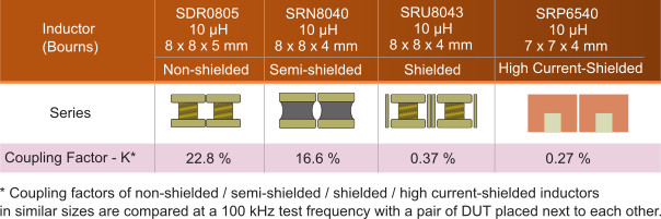
Shielded or Unshielded?
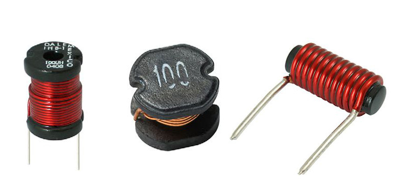
Unshielded inductors have an open magnetic circuit. Magnetic flux induced in the core by the current in the winding exits the core and extends through the air to the other side of the core where it completes the flux path. Magnetic flux outside core influences nearby circuits. Unshielded inductor with the same size as shielded one has higher saturation current and lower cost.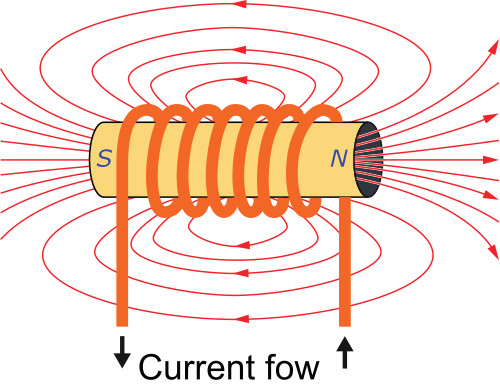
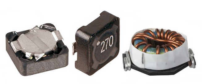
Shielded inductor is designed in a way that the magnetic flux never leaves the core, preventing flux from interfering with sensitive components that can be nearby. Shielded inductor with the same size as unshielded one has lower saturation current and higher cost.
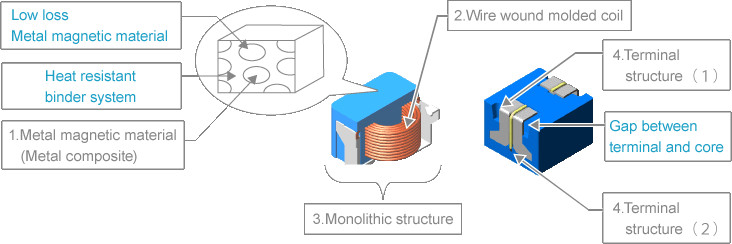
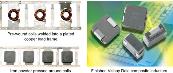
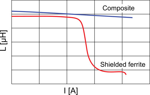
Recent progress in technology allows manufacturing of composite inductors. Inductor core is made of metal powder (iron, iron alloy or blend of iron and other metals) with particles of size 4 to 10um. Coil connected to pads is placed in a steel die that is filled with powdered metal, insuring that the powder completely surrounds the coil. The powder is then compressed by tooling from top and bottom by a pressure of about 600 MPa to form a dense magnetic core around the coil. Metal particles inside the core are surrounded by non-magnetic and non-conductive material (silicon oxide, organic binder), which makes distributed „air gap”. Inductors produced in such a way are shielded and have excellent parameters, especially high saturation current.
Shielded inductors are more expensive and have a lower saturation current (for the same physical size, core material and inductance) but they greatly reduce Electromagnetic Interference (EMI). It is almost always worth using the shielded inductors to help avoid any EMI issues. This is especially true when converter uses higher switching frequencies.
Inductance and Self Resonant Frequency (SRF)
Inductance is typically measured by small voltage (0.1 Vrms) at frequency of 100 kHz without DC bias. Typical manufacturing inductance tolerance is ±20%. SRF is the frequency at which the inductance of an inductor winding resonates naturally with the distributed capacitance characteristic of that winding. A good rule of thumb is to keep the switching frequency ten times lower than the SRF.Rated and Saturation Current
The rated current is the effective DC (or low-frequency AC) current which causes the rise of the coil temperature to a defined value, typically 40 ° C.Manufacturers use different test PCB and do not provide detailed information, which makes coil comparison between various manufacturers difficult. Temperature rise is highly dependent on many factors including PCB land pattern, trace size, proximity to other components etc. Therefore, temperature rise should be verified in final product.
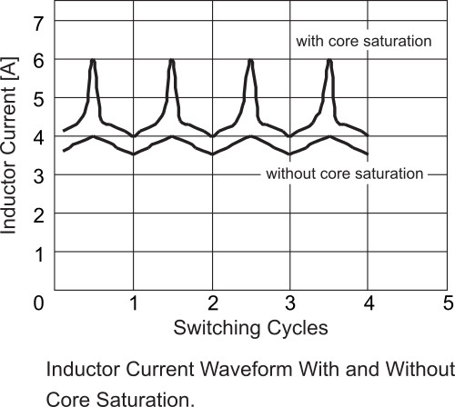
Saturation current is defined as the DC bias current that causes a specific amount of inductance decrease, usually 10%, 20% or 30% inductance drop.
Different manufacturers use different inductance drop to define saturation current, which makes coils comparison more time consuming.
Ambient Temperature Range and Maximum Coil Temperature
Multiple sources list different locations for determining the ambient temperature. Datasheets don’t clearly define place where ambient temperature is measured. Please see the article What is ambient temperature, anyway, and why does it matter? or document Semiconductor and IC Package Thermal Metrics for more information.Maximum coil temperature provides more useful information because it allows you to verify coil temperature in the final product. The coil temperature should not exceed defined value under the toughest operating conditions. Coil temperature is affected by circuit design, component placement, PCB trace size and thickness, airflow and other cooling properties.
DC resistance (DCR)
It is a DC resistance of the coil measured at room temperature of 25°C. DCR is temperature dependent. Typical winding is made of copper wire. The temperature coefficient of resistance for copper is approximately +0.4% per °C. It doesn’t look too much but for the coil temperature of 125°C it means (125-25)*0.4%=40% resistance increase.Resistance also increases with frequency due to skin effect. AC resistance (ACR) is not mentioned in the datasheet.
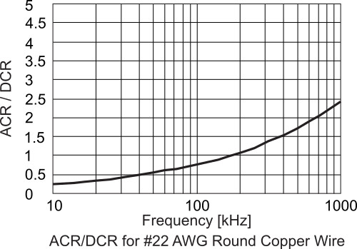
Typical design of DC/DC converter calculates with peak-to-peak ripple current through inductor 20 to 40% of the output DC current. Ripple current is triangle wave and for 50% duty cycle RMS value is approx. 0.577Ip-p. As you can see from the figure 9, for the frequency of 200 kHz is Rac/Rdc=1, total resistance at this frequency is Rtot=Rdc+Rac=2Rdc. Winding power loss will be P = Pdc + Pac, Pdc = Idc^2*Rdc, Pdc=Idc^2*Rdc.
For Iac(p-p)=0.3Idc, Pac = Iac_rms^2*Rac=(0.575*0.3*Idc)^2*2Rdc=0,06Idc^2*Rdc=0.06Pdc.
For 1MHz Rtot=Rdc+2.5Rdc=3.5Rdc and Pac=0.1Pdc.
AC resistance increases winding power loses and it is recommended to ask the supplier for loss versus frequency information.
How to Put All Together
Coil for DC/DC converter should be chosen in a way that:• it does not overheat even under the toughest working conditions
• inductance doesn’t drop below the value necessary for converter stability
• hard saturation is avoided
• converter has required size
• converter has the highest efficiency
Other converter parameters like output voltage ripple and transient response have also influence on the inductance value.
To make a quick assessment of whether a coil is suitable for a particular application, some manufacturers such as Vishay, Panasonic and Coilcraft provide web SW.
You can check:
• http://www.vishay.com/inductors/calculator/calculator/
• http://www.coilcraft.com/apps/power_tools/power/
• https://util01.industrial.panasonic.com/ww/utilities/ds/chr-vw/view03/
• https://util01.industrial.panasonic.com/ww/utilities/ds/pcc-sim/
For further information about our coils offer, please look at our web pages or contact us at sales@soselectronic.com.
Do not miss these articles
Do you like our articles? Do not miss any of them! You do not have to worry about anything, we will arrange delivery to you.


