


1.Identify your needs
What is the mounting type that is suitable to meet your application requirements?
In order to select the most optimized antenna, begin the process by confirming if the antenna will be integrated:
- Internally, for example, mobile device
- Externally which often comes with housing for protection in outdoor application and installation
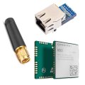
Our producer 2J Antennas offers a large selection for internal and external single and combination antenna mounting types.
Internal Single and Combination Antennas Mounting types
- ADHESIVE MOUNT FLEXIBLE
Small form factor antennas with flexibility for curved installation in devices.
- ADHESIVE MOUNT RIGID
This mounting type is ideal for flat surface installations, using an industrial-grade adhesive layer.
- SURFACE MOUNT CERAMIC
Due to high-quality ceramic, this surface mount is ideal for a wide range of environments and is compatible with surface mount technique (SMT), allowing for easy PCB integration into small devices. - SURFACE MOUNT FIBERGLASS
Fiberglass material allows for the small antenna sizes while offering cost-effective solutions to device designers and is compatible with surface mount technique (SMT) installation. - THRU-HOLE MOUNT CERAMIC
The thru-hole mount is typically in the center of the antenna offering extra security for installation for in-device integration.
- SNAP-IN MOUNT MODULE
Locks the antenna in place, prevents unwanted rotation and facilitates rapid antenna installation and replacement
- SCREW MOUNT MODULE
Modular antennas that can be installed on PCB standoffs
External Single and Combination Antennas Mounting types
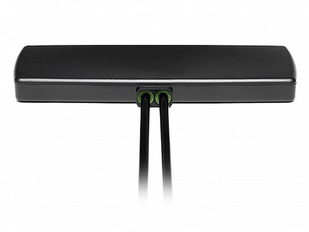
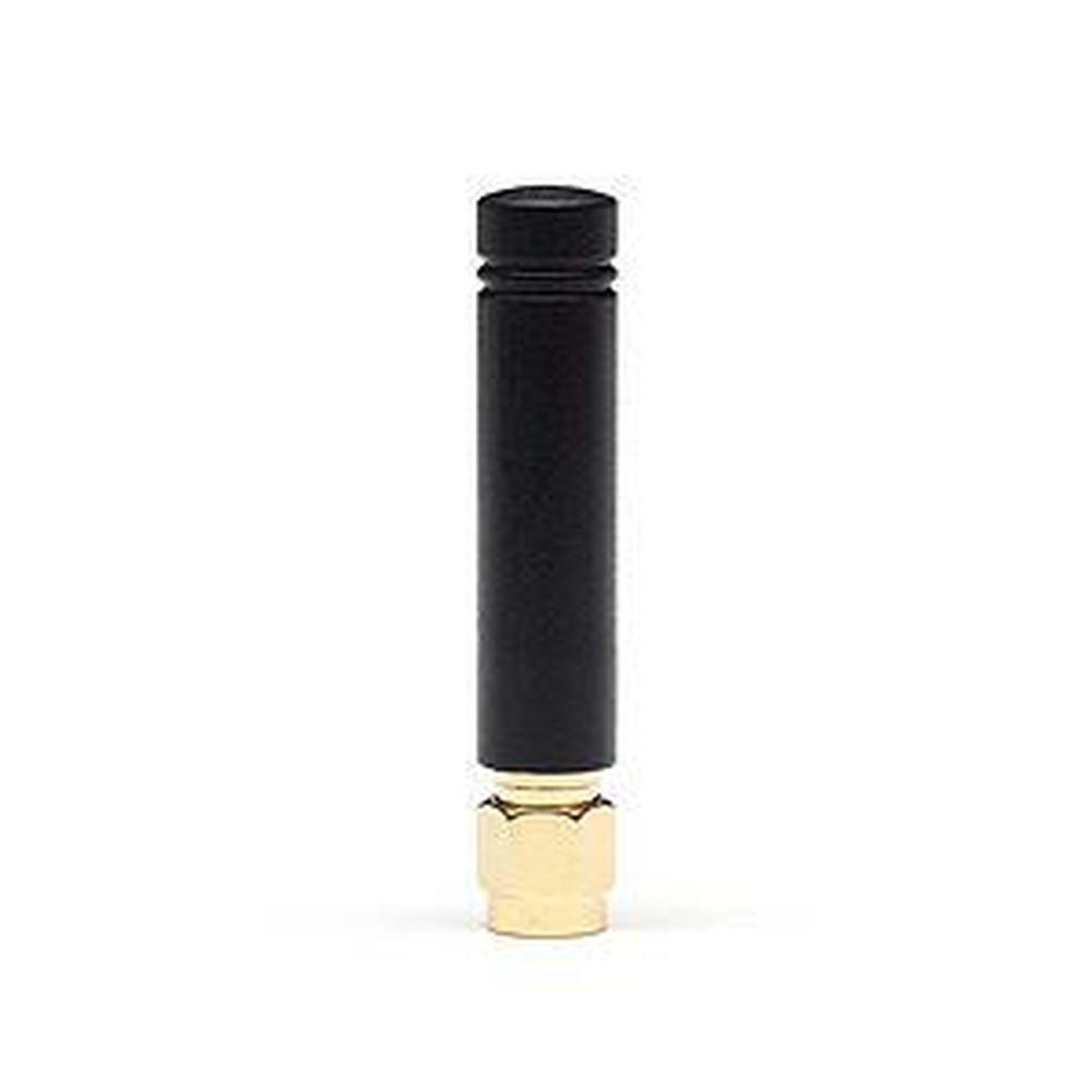
- CONNECTOR MOUNT
Typical for antennas that require direct PCB mounting solution on devices - ADHESIVE MOUNT
Using a high-grade adhesive option makes it ideal for quick mounting applications - SCREW MOUNT
Advantage is a secure and permanent installation also in outdoor extreme conditions. - MAGNETIC MOUNT
Offers flexibility for temporary installation, strong enough for permanent installations - WALL MOUNT
Can be used for indoor or outdoor installations - POLE MOUNT
recommended for marine or construction applications. - MAGNETIC/ADHESIVE MOUNT
Offers flexibility for temporary installation, strong enough for permanent installations. - WALL MOUNT
Can be used for indoor or outdoor installations - POLE MOUNT
recommended for marine or construction applications - MAGNETIC/ADHESIVE MOUNT
Offers the option of magnetic or adhesive mounting for external installations, especially for non-magnetized metal surfaces - WALL/ADHESIVE MOUNT
Offers the option of wall or adhesive mounting for building wall installations - VELCRO/ADHESIVE MOUNT
a solution for temporary use of the antennas
Frequency and Wavelengt
What is the frequency and why is it so important? The wireless band designated for a device to operate through is called frequency. Antennas are designed to have a range of frequencies to operate within. As an example, if a device is tuned to use Band 17(700MHz), the corresponding antenna must operate within 704 and 746 MHz for transmission and reception.
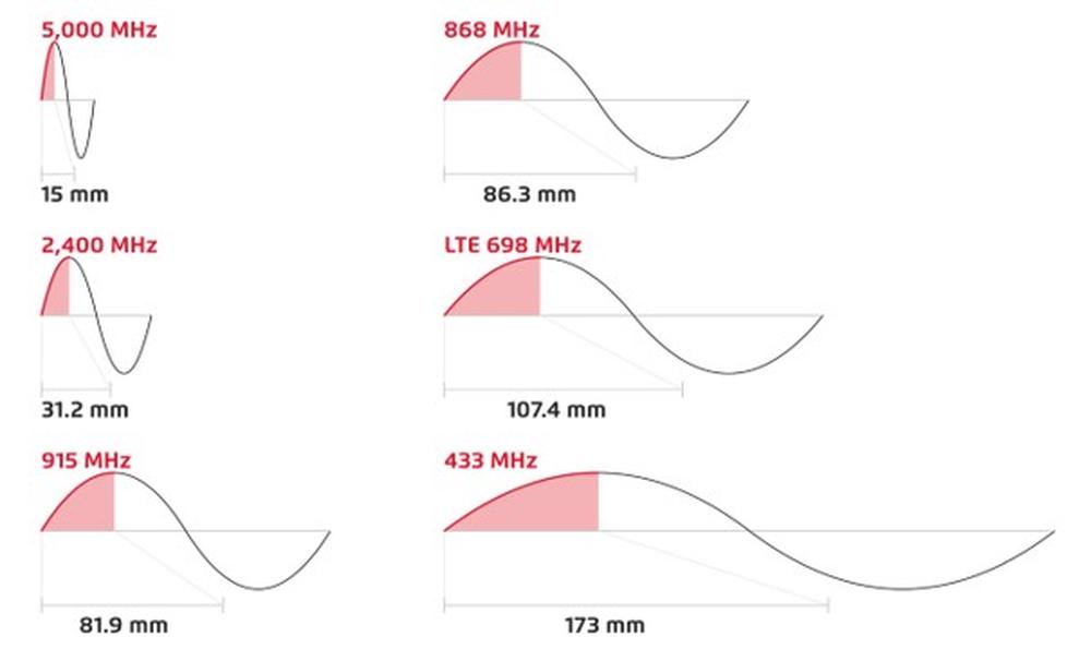
Are you sure, you know what is the wavelength? The wavelength is the distance radio waves travel during one cycle. Designing an antenna quarter wavelength long will provide the best efficiency and deliver the highest signal quality.
Quarter wavelength is calculated with the following formula:
Quarter Wavelength(mm) = (75/ FreqMHz)*1,000
IMPORTANT: 4GLTE and 3G/2G antennas have the potential to be used in applications requiring ISM standards. 4GLTE range specification of 698-960MHz and 3G/2G from 824-960MHz, meaning the ISM 868MHz standards operate from 863-870MHz and are located within the 4GLTE and 3G/2G range. The same applies for ISM 915MHz standards that operate within 902-928MHz, or dual band 868/915MHz.
To ensure proper compatibility, please contact our SOS electronic sales department. For further analysis, we will contact directly the producer, 2J antennas.

Fig.1, Examples of 1/4 wavelength; Frequency / Length graph
Standards & Bands
In our portfolio you can find 2J antennas that operate within many global standards. As example, our 4G LTE antennas are compatible with Cat-M, Cat-X, Cat-NB, NB-IoT and also SigFox and LoRa, known as LPWA market. The same analogy can apply often to other frequencies. As an example, WIFI antennas can be used for SigFox or LoRa in the 2.4 GHz spectrum.
GNSS antennas are available with pre-filter, mid-filter or no-filter to meet the customers' different requirements.
The pre-filter offers the highest resistance and best reception and therefore is standard on all GNSS antennas. It is important to compare active gain and noise on the amplifier of GNSS antennas.
Antenna standards from portfolio:
- 5GNR/4GLTE/FirstNet/CBRS/LPWA/3G/2G
- 4GLTE/FirstNet/NB-IoT/Cat-X-Mx-NBx/LPWA
- 3G/2G
- 2.4-5.0GHz WiFi/Bluetooth/ISM
- IRIDIUM
- GPS/GLONASS/BeiDou/QZSS/Galileo
- 433/868/915MHz/LPWA/Sigfox/LoRa /RFID/ZigBee/ISM
- TETRA/UHF/PMR/LMR
- 169MHz/ERMES/VHF
- DECAWAVE
- DSRC/C-V2X
- ORBCOMM
- AIS
- DAB
- HDTV/DVBT
- AM/FM
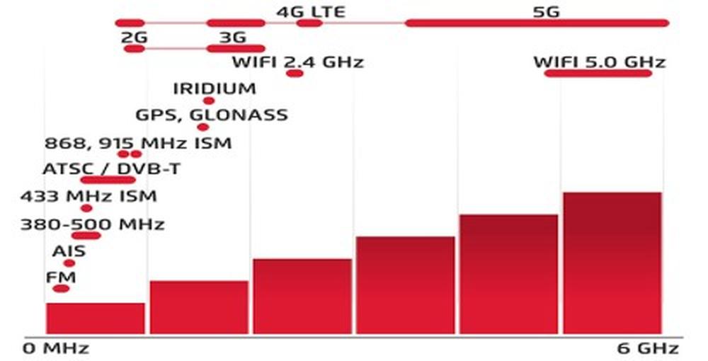
Fig.2, Frequency showing Standards Graph
2.Terms Explanation
To make the choice easier, we have highlighted some of the key points that require closer attention. The most effective way is to compare the favourite antenna to other products. However, do you clearly understand the parameters in which the antennas are tested and measured to achieve the most reliable performance results?
Testing Parameters
Testing parameters and methods can vary from manufacturer to manufacturer. Testing methods should always be fully disclosed such as free space, metal plate, plastic plate, glass, etc. Installing antennas outside of testing parameters will result in undesired antenna performance.
For example, if a screw mount antenna is measured in free space showing optimal performance results and is installed on a metal surface in the customer device, the antenna will not operate as expected. 2J Antennas will always disclose the complete measurement conditions to assure our customers get the most accurate data making the in-device integration of an antenna successful. In order to make a smart product selection between two manufacturers, we encourage that all testing should be completed with a standard length and high-quality cable in order to optimize antenna performance results. No alterations during testing such as shorter or no cables should be performed. This will result in inaccurate efficiency, peak gain and average gain results.
Return Loss
The return loss is measured in decibels (dB) and represents how much energy is transferred from the device to the antenna. It can help to can help to estimate the bandwidth and operating frequencies.
The lower the measurement the better. For a 50 Ohm system, it is recommended to have a minimum of -5dB or better measurement.
VSWR
Voltage Standing Wave Ratio (VSWR) is used to measure how much energy is transferred from the device to the antenna but with a different mathematical scale than the one used for Return Loss.
The lower the measurement the better, meaning closer to a 50 Ohm system and it is recommended to have a maximum of 3.5 VSWR. Please review the table below to learn more about the relationship between Return Loss and VSWR as well as other RF parameters and values.
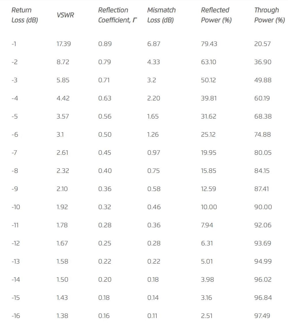
Table 1, Return Loss to VSWR Conversion Table, and more RF parameters.
Bandwidth
Efficiency
Antenna efficiency (radiation efficiency) is the most important parameter of an antenna in mobile communications. It is a measure of the electrical efficiency in which a radio antenna converts the radio frequency power received into radiated power. In other words means how much energy is radiated from the antenna to the air, how good is the antenna to radiate the energy.
(100% means all energy radiated, 50% means half energy radiated, the minimum recommended is 25% but in some cases can go down to 10%, but the higher the better).
Peak Gain
The most crucial parameter in mobile communication is antenna efficiency followed by peak gain.
Antenna gain is the measurement of an antenna's ability to direct or concentrate radio frequency energy in a particular direction or pattern. This is typically measured in dBi (Decibels relative to an isotropic radiator). Efficiency measures how much energy is in the air radiating in all directions, while peak gain is only measured in a single direction. While in fixed communication the most important parameter is the peak gain, since all the energy must be concentrated in one single direction.
This value comes from a single point in the radiation pattern being the maximum point in the 3D sphere.
Average Gain
Similar to efficiency, the average gain is represented with a different mathematical scale (dB) and takes into consideration any mismatch losses. 100% is 0 dB which is maximum radiated energy, 50% is -3 dB which is half of the radiated energy, etc. Please see below table for the relationship between efficiency and average gain:
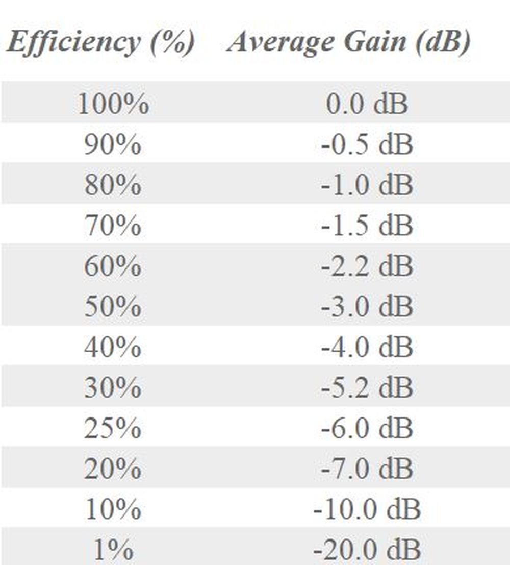
Table 2, Efficiency/ Average Gain Table
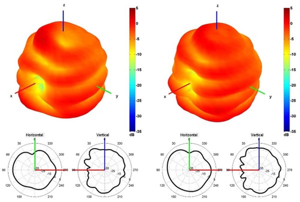
Radiation Patterns
The radiation pattern of an antenna is the strength of radio waves transmitted by the antenna traveling in different directions and angles.
Omnidirectional antennas offer a 360-degree doughnut-shaped radiation pattern that is uniformly distributed in all directions and are ideal for connecting devices that are on the same plane and to either side of each other.
Hemispherical antennas distribute their radiation over a hemisphere (half of the space).
Directional antennas radiate into one targeted direction allowing for longer transmission distances with less interference.
The picture shows how the energy is being radiated to the air in 3 dimensional or 2 dimensional pattern. In 2D graph pattern, the horizontal and vertical planes are shown. Fig.3.

Fig.3, Radiation Pattern 3D and 2D Graph
Polarization
Polarization is the orientation of the electric field of an electromagnetic wave. The two most common polarizations are linear and circular.
With linear polarization, the electric field vector stays in the same plane were in with circular polarization, the electric field vector is rotating with circular motion completing a full turn for each RF cycle. This rotation can be completed right-hand (RHCP) or left-hand (LHCP).
Measurement and changes of polarization are determined in which the wave transmits through the environment from the transmitting to the receiving antenna.
3.Specification
Ground Plane
A ground plane is a surface area or metal that acts as a conductor and reflects the radio waves from other antenna components. The shape, size and the required clear area of the ground plane play an important role in determining radiation characteristics and gain.
Our portfolio of 2J Antennas offers both, ground plane dependent and ground plane independent antennas.
Low-frequency antennas such as broadcast antennas accept large conducting masses such as the earth or ocean as a sufficient ground plane. For very high frequency (VHF) and ultra-high frequency (UHF) antennas, the ground plane can be smaller and a metal disk, screen or wire is used as a ground plane. In automotive, marine and air equipment metal housing (car / airplane / boat) can serve as a sufficient ground plane.
As a general rule, the conduction surface must be at least a quarter of the wavelength of the radio waves in diameter and in ideal condition the bigger the ground plane the better control of the electrical performance is achieved.
Maximum Input Power
The Maximum Input Power is the maximum amount of power (in Watts) that can be transmitted to one antenna port without damaging it while maintaining performance.
Cable and Connector Types
The correct selection of RF cable and connector types is critical to proper antenna function. The connector serves as a mechanical connection between the antenna and RF system and the cable is the transmission line for radio frequency signals connecting transmitters and receivers. The cable lengths impact signal quality and strength.
Selecting a high-quality cable and connector that is compatible with the antenna will ensure optimal antenna performance. When considering a product, it is important to determine the correct connector gender, polarity and geometry as well as the cable length prior to a quote request.
We are very happy that you are interested in antennas. Read the sequel as well:
2J Antennas is our longstanding partner in the field of antennas. Their valuable experience is a great asset for us as a project-oriented distributor. Many of our customers' projects have been built taking advantage of their wide range portfolio, as well as custom-made solutions from their professionals.
If you are looking for the perfect antenna, please contact us. We will be glad to help you with the selection at sales@soselectronic.com.
Source: 2J Antennas
Do you like our articles? Do not miss any of them! You do not have to worry about anything, we will arrange delivery to you.

 2J ANTENNAS")


