


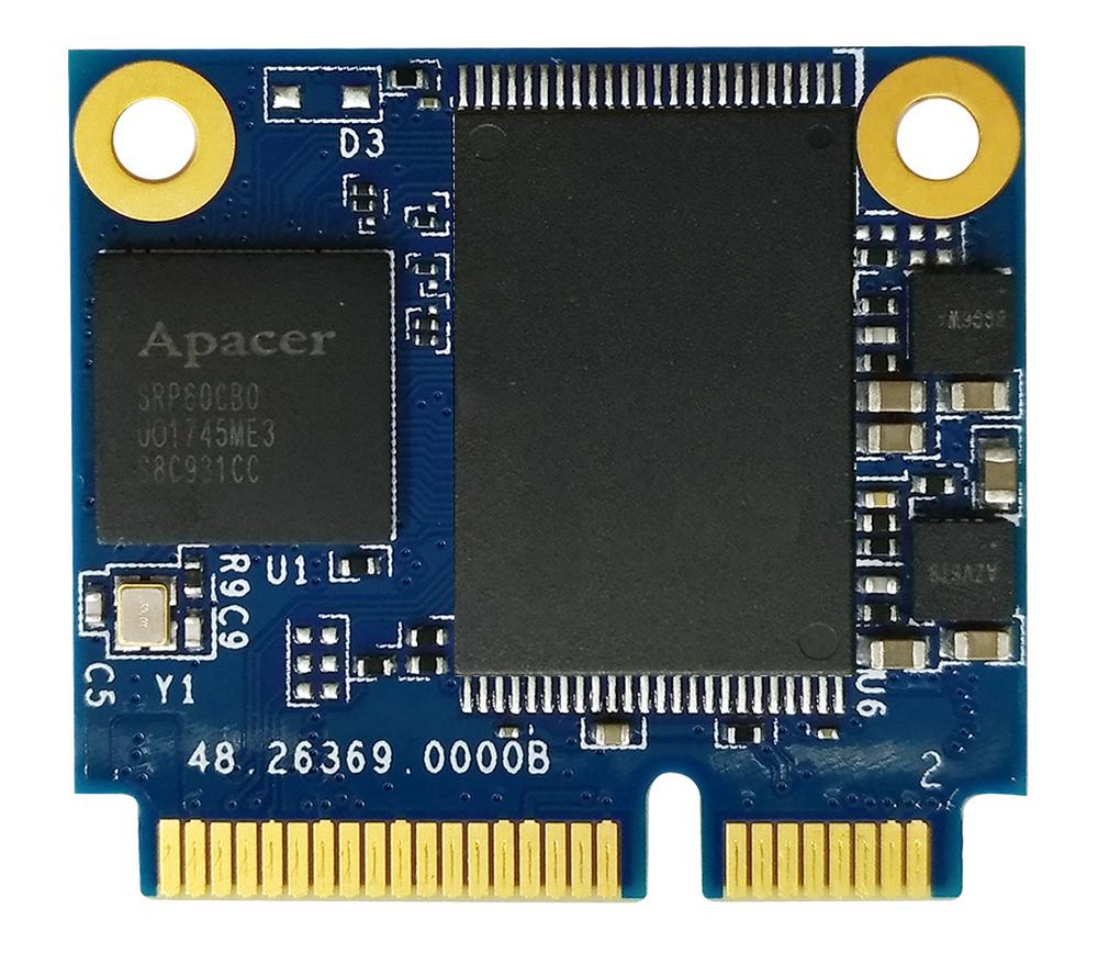


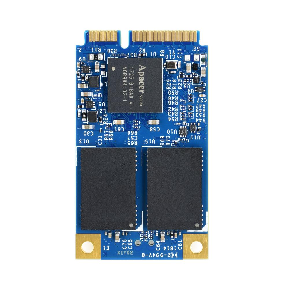
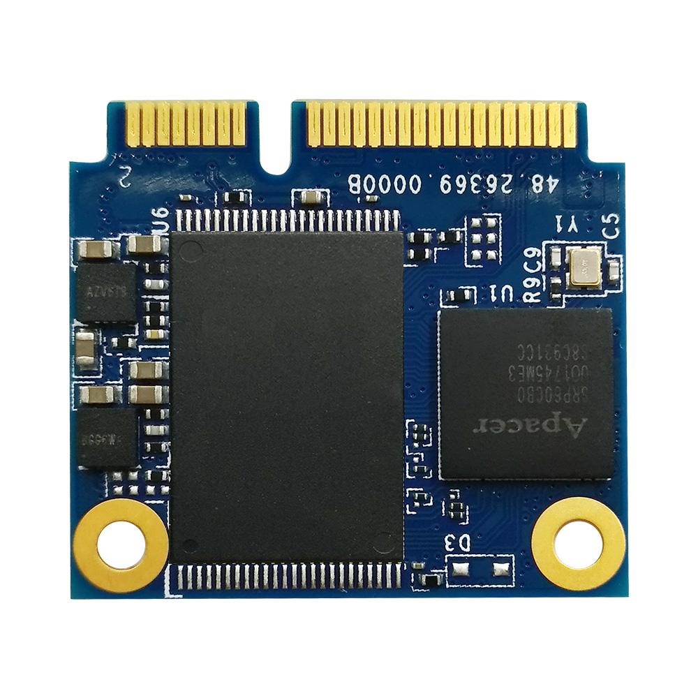
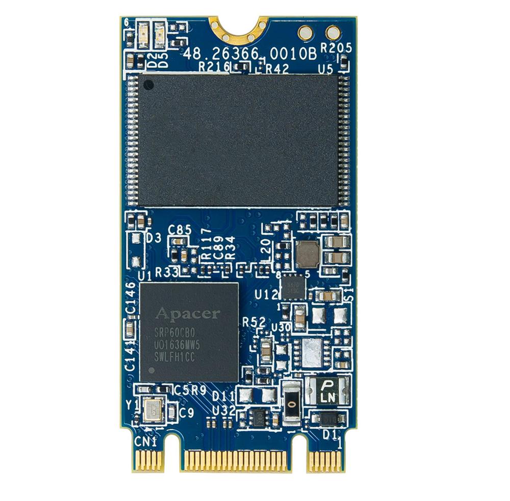
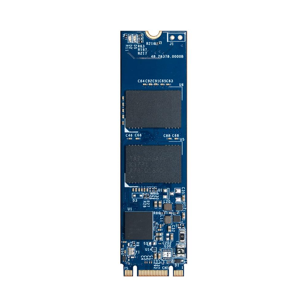
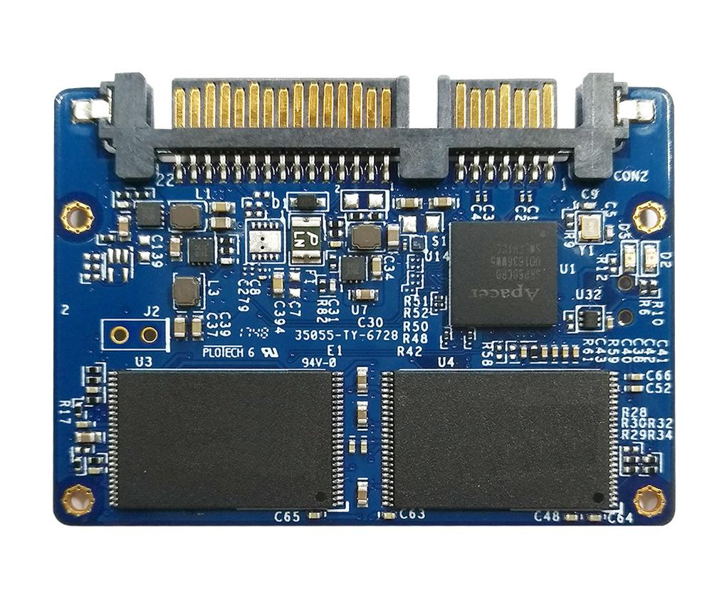
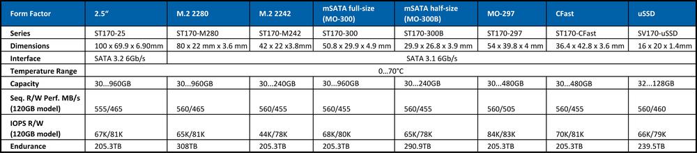
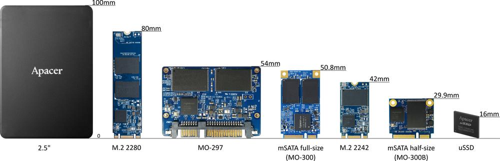
Apacer introduces a new ST170 series in 2.5" SSD, M.2, mSATA, MO-297, CFast and uSSD form factors.
To make products reliable and simultaneously provide high performance, they use:
• Error Correction/Detection
• Power Failure Management
• Flash memory Bad-Block Management
• Global wear levelling – all spare blocks in all flash chips in the product are managed together in a single pool. Controller tries to distribute the writes evenly to all flash memory blocks. You can judge the efficiency of algorithm from SMART attributes Max. erase count and Avg. erase count.
• End-to-end data protection - a feature that extends error control to cover the entire path from the host computer to the drive and back, and ensures data integrity at multiple points in the path to enable reliable delivery of data transfers
• SMART (Self-Monitoring, Analysis and Reporting Technology)
• Thermal sensor – regularly check SMART attribute Temperature and decrease SSD workload to avoid rising SSD temperature above 70°C
• Page-level flash translation layer
• Hyper cache technology - portion of the available capacity is used as SLC (1bit-per-cell) NAND flash. Only two values are written (0, 1) instead of eight.
• Over-provisioning - certain portion of the SSD capacity is reserved exclusively for increasing garbage collection (GC) efficiency, especially when the SSD is filled to full capacity or it is under heavy mixed (sequential-random) workload.
• TRIM support - the command enables the operating system to inform the SSD flash controller of blocks that contain unnecessary data, typically data that the operating system has deleted. The controller then erases the unnecessary blocks and releases them for use.
Error Correction/Detection
When application writes data to SSD, flash controller writes the data, firmware information and ECC (error correction code) to flash memory. Controller writes 40-bit BCH (Bose-Chaudhuri-Hocquengham) ECC per 1KB of data for SSD from SM210-25 series, for example. When controller reads the data from flash memory, it uses ECC to check the data validity and correct errors. ST170 series uses low-density parity-check (LDPC) as ECC code. For normal reading that doesn´t modify reference voltage connected to memory cell gates (hard decoding), it provides slightly better error correction than BCH code. If controller can’t correct errors in data, soft decoding mode is used. In this mode, the controller reads the data from the flash multiple times with different reference voltages connected to memory cell gates. Soft decoding has a much better error correction capability, but multiple readings mean slower read performance.
You can check Error Correction/Detection status by reading the SMART attribute Bad Cluster Table Count.
Flash Memory Bad-Block Management
When a flash memory chip leaves factory, it contains a minimal number of initial bad blocks. There is no currently known technology that produces flash chips free of bad blocks. In addition, bad blocks may develop during program/erase cycles. Since bad blocks are inevitable, the solution is to keep them under control.To check the current bad block count, the user should read SMART attribute Total later bad block count.
Power Failure Management
The best way to prevent damage to data during a sudden power outage is to prevent its occurrence. It is not always possible, and therefore ST170 series provides several protection mechanisms to avoid data corruption. 1. Mapping Table Protection The mapping table contains records that map logical addresses to the physical address of flash memory pages. Page-level mapping provides excellent random write speed but requires a lot of RAM to store mapping table. During the write operation, the controller writes data and mapping information to flash and then it updates the table in RAM.In case of power loss, there isn’t enough time to write mapping table to flash, so it is lost. After power resume, the controller sequentially reads every NAND flash block, retrieves the logical address mapping and rebuilds the mapping table. If the mapping table is not successfully rebuilt in the initial reading, the controller keeps reading until the mapping table is recovered.
2. Last Write Protection
Flash memory can’t be overwritten, so to update page P1 in block B1 firmware writes new version P1’ to block B2. If a power failure occurs during the writing of the page P1’, operation may or may not finish successfully. After power resume, the ECC firmware detects and if possible, corrects the error in page P1’. If correction is impossible, firmware previous version P1 is used and garbage collection algorithm takes care of the invalid P1’ page.
3. HyperCache
Series doesn’t use DRAM cache which, in case of power blackout, losses data because there isn't enough time to write data from cache to flash. Hyper cache is used instead of it.
Check if bad block count increases (SMART attribute Total later bad block) when attribute Unexpected Power Loss Count increases. If so, you should make precaution to avoid power loss occurrence.
SMART
SMART is an abbreviation that stands for Self-Monitoring, Analysis and Reporting Technology. It monitors the important SSD parameters for taking proactive measures to prevent its failure.Full list of supported parameters are provided in datasheets. The meaning of some important attributes was described above. The other important parameters are:
Lifetime left – value in percentage, 100% means a new SSD, 0% fully utilized - such SSD should be replaced immediately. ST170-25 doesn’t provide this information, however attribute Avg. erase count can be used to estimate lifetime left.
Lifetime left = (1 - Avg. erase count/PE Cycle) x 100, PE Cycle=3 000 (the same value as for MLC flash based products)
SSD Protect Mode
• 0: R/W – normal status
• 3: Read Only
• 7: Unusual Read Only (Occurs when free blocks are insufficient or encountering excessive later bad blocks)
SSD protects itself by setting to read-only mode to avoid data corruption, if Avg. erase count exceeds 3 000 PE cycles or event described for parameter value = 7 occurs.
SATA PHY Error Count - indicates problems with communication. They can be caused by defective cable or connectors for example.
We have added the new ST170 Series to our assortment and it will be available upon request.
We offer you the opportunity to order samples for testing for discount price. For information about available models, please visit our website.
If you are interested in other APACER products or if you need help, please contact us at apacer@soselectronic.com
Do you like our articles? Do not miss any of them! You do not have to worry about anything, we will arrange delivery to you.


